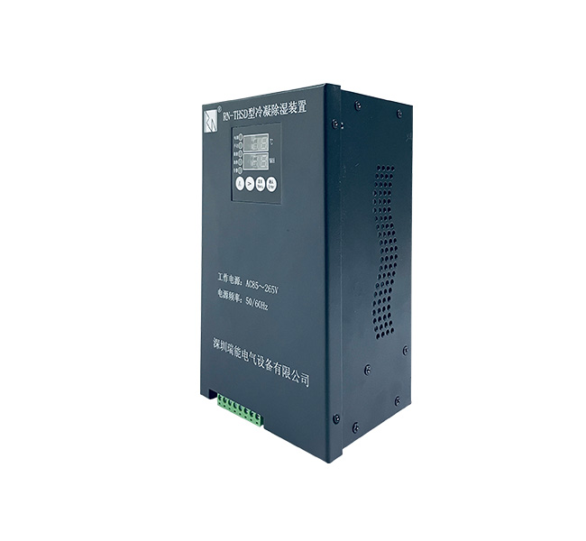
1. An overview of the
Power production equipment is an important part of today's industrial production process, the degree of automation is getting higher and higher, environmental temperature and humidity is an important factor affecting the normal work of electrical equipment. High voltage switchgear, terminal box, all kinds of distribution cabinet equipment spacing is small, in high temperature and humidity weather is easy to cause insulation drop and even electrical flashover, resulting in the grounding of AC and DC from time to time, causing adverse effects on the safe operation of equipment, serious cause equipment burn down, cause safety accidents. Therefore, it is necessary to take certain measures to improve the moisture-proof performance of the equipment, to ensure its internal dryness, and to ensure the safe and stable operation of the equipment.
RN -- THSD series is an intelligent humidity controller with dual display and control, also known as condensation dehumidification device. It mainly uses the Pertier effect and the refrigeration sheet as the core component to make the moisture in the air condense on the surface of the condensate, and then it is discharged out of the box through the drain pipe. In this way, the moisture in the air in the electrical cabinet is continuously reduced, so that condensation will not occur again, which can effectively prevent the occurrence of creepage and flashover accidents caused by low temperature, dampness or condensation. The problem has been fundamentally solved.
2.Technical parameterTechnical parameter | Index |
Measure | Temperature range | -40℃ ~ +125℃ |
Humidity range | 0 ~ 100%RH |
Display resolution | 0.1 |
Control type and parameters | Condensation dehumidification heating dehumidification (extended function) | ≥Set value start (control parameter range adjustable, factory default parameter); can be set by the user freely |
Accuracy | Temperature | ±0.3℃(25℃時) |
Humidity | ±2%RH |
Power Supply | Voltage | AC 85~265V |
Power waste | Static ≤ 12W, dynamic ≤ 70W |
Dehumidification capacity | 350ml/24h (@30℃/Rh85%) |
Drainage mode | Φ 8 water pipe direct drainage |
Communication | One channel RS485 Modbus RTU protocol (optional, extensible) |
Function | Digital display data, real-time monitoring of the current environment temperature and humidity, load independent control, alarm indication, data communication (this option can be expanded) |
Control output and contact capacity | Manual control and automatic control, AC 250V / 8A |
Insulation resistance | ≥100MΩ |
Power frequency withstand voltage | Power input to output / power supply and enclosure accessible metal parts; 2kvac 1 min |
Environmental Science | Work environment | -20 ℃~ + 65 ℃, relative humidity < 95rh, no corrosive gas and dust |
Storage environment | -20℃ ~ +55℃ |
Appearance | Size | 191X113X80mm(Long, wide, deep) |
3. Product work and instructions
3.1. Manual control
Under normal working condition, press the "Up" button for more than 3 seconds to start the heater manually, and the manual indicator and heating indicator will be on. Long press "to the right" is more than more than 3 seconds, manual force dehumidifying device into the state, led light for manual and dehumidification indicator light, for the sake of safety, manual heat or dehumidification start after about 1 hour or in manual state again after long press the corresponding button, corresponding to its heating and dehumidification function will be closed manually, device into the state of automatic measurement and control.
3.2. Automatic control
After the device is powered on, it enters the automatic measurement and control state. The current temperature and humidity are compared with the threshold value. To adjust the temperature and humidity.
Automatic defrosting: When frosting occurs on the cold end face, start the external heater, and turn off the heating when the temperature rises to more than 5℃.
Overtemperature: When the temperature of the hot end surface or the ambient temperature exceeds 85℃, stop the dehumidification and send an alarm.
3.3. Measurement
In the measuring state, the current ambient temperature, humidity value and the temperature of hot and cold end face can be displayed at the same time
3.4. Control Settings
Factory default setting :(users can set it according to site conditions)
Start dehumidification at 75% humidity, close dehumidification at 65% (return value 10%)
Start the heater at 5℃ and close the heater at 15℃ (return value 10℃)
Start the fan at 45℃ and close the fan at 37℃ (return value is 8℃)
Back-off value: In the process of temperature and humidity control, the difference between the temperature or humidity value when the actuator starts working and the temperature or humidity value when it stops working is called the back-off value.
(Note: the total value of the temperature lower limit setting value plus the temperature backlash value must not be greater than the temperature upper limit setting value, or the total value of the temperature upper limit setting value minus the temperature backlash value must not be less than the temperature lower limit setting value, otherwise the setting is invalid and the set data cannot be saved, and the modification and preservation of parameters can be observed after returning).
4. Display description of fault alarm code
The device detects the internal important devices. If there is a failure, alarm code and alarm contacts can be displayed through the alarm indicator light and LED (both interfaces are passive interfaces).
Alarm event | Warning light | Alarm relay | Heating relay | Dehumidification | LED code |
Environmental sensor failure | Chang Liang | Close | To break off | Stop it | u |
Failure of cooling plate | Chang Liang | Close | To break off | Stop it | c |
Fan failure | Chang Liang | Close | To break off | Stop it | n |
Over temperature alarm | Chang Liang | Close | To break off | Stop it | ? |
Frosting tips | Chang Liang | Close | Close | Stop it | E |
5. System setting mode
Enter/exit system setup mode:
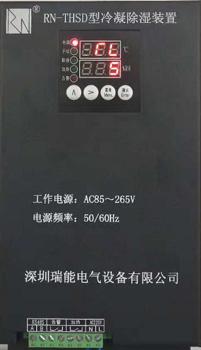
5.1. Enter setup mode: under normal circumstances, the normal and control work of the controller, press Enter to confirm key at this time, Enter the main menu, bar LED display on the PSd, twinkle bar under 000, according to request for a password, (wrong password can Enter the view parameters such as, but not to change the operation, must be conducted for the correct password to change operating parameters) the default password is 001, see figure 1 the following reference operation method,
From left to right, the first key is "Up" (increment), the second key is "Right", press "Right" to move to the third place, press "Up" to change to 001, and press "OK" to enter the sub-menu.
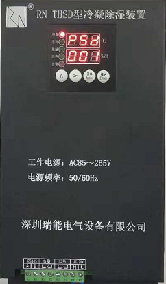
5.2. Temperature setting
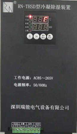
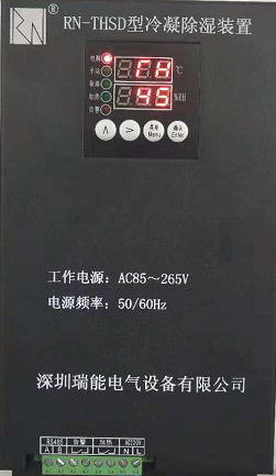
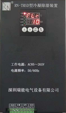
Press "OK" to enter the temperature (T) sub-menu, and set the temperature upper limit (TH), temperature upper limit back difference (THR), temperature lower limit (TL) and temperature lower limit back difference (TLR). After setting, press the "OK" button to save.
5.3. Humidity setting
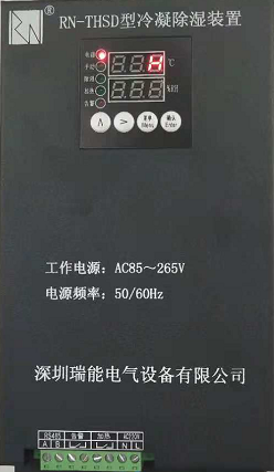
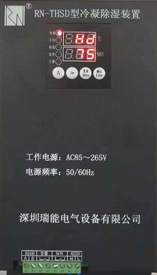
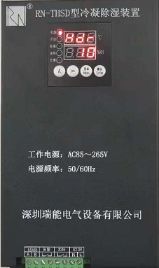
Press "OK" to enter the humidity (H) sub-menu, and check the humidity upper limit (HD) and humidity return value (HDR).
Make Settings. After setting, press the "OK" button to save.
5.4. System parameter setting
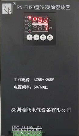
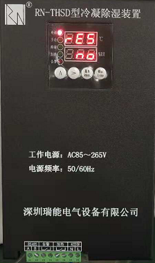
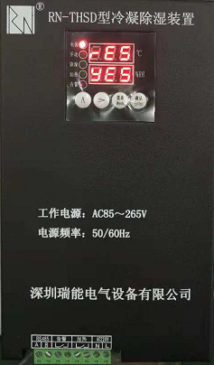

Restore factory Settings (RES) : Select Yes to restore factory Settings, select No to customize Settings;
Ver menu: View version;
After setting, press the "OK" button to save.
5.5. Exit Settings Mode
After returning to the item selection sub-menu, press "MENU" button to exit the system setting mode and return to the normal working state. In the menu setting mode, the "Do not operate" button will automatically return to the normal working state after more than 1 minute. In the parameter modification state, the parameters saved without pressing the "OK" key will not be saved.
6. Installation mode and terminal wiring diagram
The installation mode can be track type, screw fixed type, floor type. Any installation method must keep the device vertical and avoid tilt.
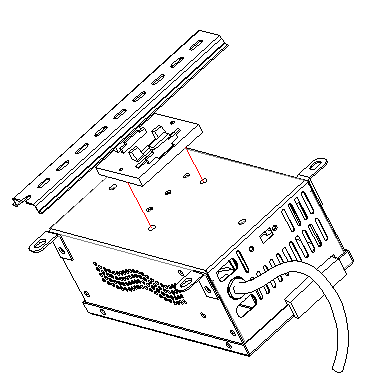

Orbital
The device can be directly clamped on the 35mm standard guide rail or fixed on the standard guide rail with screws.
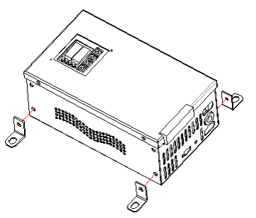

Screw fixed
4 fixing strips are first installed on the device, and then fixed on the mounting plate or bracket with the bolt of M6, so that the shell is suspended or installed on the ground.
Special note: there should be a certain height drop between the device and the water pipe, the water pipe should not be circled, the middle should not be concave, and the water pipe should not be S-shaped. It should be extended naturally to ensure that the water flow can be smooth and prevent the water pipe from blocking the device.
6.2. The terminal wiring diagram of the device is as follows:

7. Dimension drawing (unit: mm)
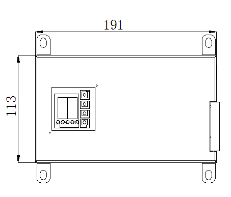
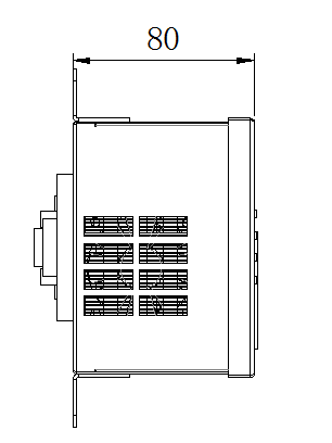

Device dimension drawing Dimension drawing of device opening
8. Precautions for use
1. Each product includes: 1 device, 1 drainage hose, installation guide rail and screws, etc.
2. Under the premise of reading the instruction manual carefully, make sure that your wiring is correct. Do not connect the wiring under the condition of power on. Do not connect the overload execution equipment.
3. After the vertical installation of the device, the drainage hose position should be reasonably arranged to prevent the device failure caused by poor water flow.
4. Automatic mode should be selected for on-site operation of the device.
5. Do not collide or move the device at will during operation
6. Do not remove or tilt the operated device immediately. Because the internal refrigerating plate or water drops are still attached, it should be dried after power off for 30 minutes before moving or disassembling.
9. External heater (optional)
We recommend the heater: AC220V/ 50Hz
Electric heater: one is DJR type (aluminum alloy type), the other is DJB type (silicon rubber type), power 50W, 75W, 100W, 150W, 200W, 300W.
Heater Selection Table
Model | Working voltage(V) | Heating power(W) | Dimensions(mm) | Distance between mounting holes(mm) |
DJR-A-1 | 220 | 30-250W | 158*75*24 | 55 |
DJR-A-2 | 220 | 100-500W | 200*104*26 | 55 |
DJR-B-1 | 220 | 30-250W | 132*85*23 | 55 |
DJR-B-2 | 220 | 50-300W | 163*100*28 | 55 |
DJR-C-1 | 220 | 50-300W | 155*100*23 | 55 |
Note: the heater size may be different from the manufacturer, please refer to the physical size. The recommended parameters are for reference only.


